The SPACE GASS steel connection design module lets you design or check any of the connections in a structural model. Design actions are automatically obtained from the analysis results and multiple load cases can be considered simultaneously.
Operating the module simply involves you selecting the members to be connected and then choosing the desired connection type. The connection is immediately designed and presented to you as a fully rendered 3D image in the connection viewer. From there you can examine it in more detail by zooming, panning or rotating, or you can switch to an annotated 2D elevation that describes the various components of the connection. Other buttons allow you to turn on or off various parts of the connection so that you can see components that may be partially hidden.
If you want to modify the connection or change it to match an existing connection that needs to be checked, you can do so by simply editing the bolt, weld, plate, cleat or dimension data. Each time you make a change the connection is automatically re-checked and the 3D image is updated so that you can see exactly what is happening as you go.
Note that if you have SPACE GASS 11.09 or later you can run the new steel connection design module in a free trial mode that lets you try it out.

Connection design video
Fully Integrated into SPACE GASS
As with all SPACE GASS modules, it is fully integrated into SPACE GASS and automatically extracts all of the required analysis results for the load cases you specify.
Complies with AS4100 and the Latest ASI Design Guides
The connections are designed to AS4100 in accordance with the recommendations of the latest ASI Design Guides.
Design and Checking Modes
You can run the module in design or checking modes.
To set up a connection for design, you graphically select the one or two members involved in the connection and then choose the desired connection type. No additional information is required and you can then move on to the next connection.
To set up a connection for checking, the procedure is the same except that you must also specify the bolt, weld, plate and stiffener components that make up the connection to be checked. Alternatively, you can click the design button to obtain components that work and then modify some of them to suit your checking requirements.
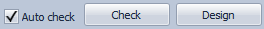
Auto-Check Mode
If you tick the "Auto check" option, then while you are setting up your connection, it is checked automatically every time you change an input parameter. This is very handy if you want to get immediate feedback on the changes you make.
Immediate and Batch Processing
While setting up your connections, you can design or check each one on the spot, or you can process them all later by letting the connection module cycle through them all.
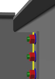
Fully 3D Rendered Models
Each connection is displayed as a fully 3D rendered model that gives you a realistic representation of the connection. You can zoom, pan and rotate the connection as you set it up so that you can see its exact geometry and how all the components fit together.


2D Cross Sections and Side Elevations
You can generate 2D elevations and cross sections of your connections and export them to the common drawing formats.


Connection Manager
The connection manager is the heart of the module and allows you to re-design or re-check all of your connections, view them, edit them or generate reports.

Bolts, Welds, Plates and Stiffeners
When in design mode, all bolts, plates, welds, stiffeners and cleats are selected from standard libraries and sized according to the most optimal solution. If no suitable library component is available then a custom component is used where applicable.


Open Connection Types
Tubular Connection Types

