Save Buckling Mode File
The Save Buckling Mode File tool creates a new model whose geometry has been displaced to match one or more buckling mode shapes from a completed buckling analysis. It is typically used to build a geometrically imperfect version of a structure, for example to seed a non-linear analysis with an initial imperfection that follows the way the structure wants to buckle.
Every node in the new model is moved by an amount taken from the selected mode shape or shapes, while all other structural and load data is carried across unchanged. The result is a standalone SG model file that you can open and analyse in the normal way.
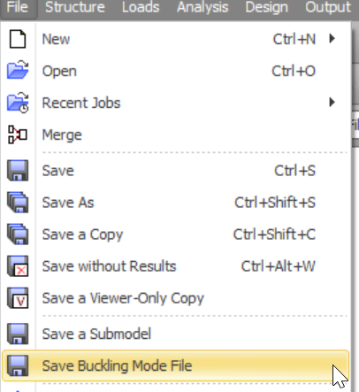
The tool is on the File menu: File => Save Buckling Mode File. Selecting it opens the Save Buckling Mode Shape dialog described below.
Prerequisites
A buckling analysis must have been run, and buckling mode shapes must exist for the load case you want to use. Mode shapes are produced by the SG-X solver, by the Wavefront solver (either theory), or by the Paradise solver using Classic Eigensolver theory. They are not produced by the Paradise solver using Signcount Eigensolver theory. If no mode shapes are available, the tool reports that a buckling analysis is needed.
Save Buckling Mode Shape dialog
The Save Buckling Mode Shape dialog collects the output file, the load case, and the list of modes to apply.
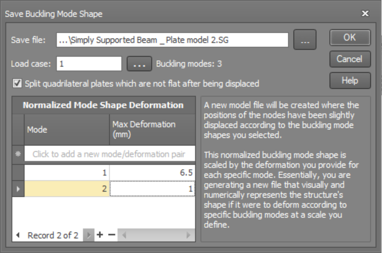
- Save file. The path and name of the new model file to create. It cannot have the same name as the current job.
- Load case. The buckling load case to take the mode shapes from. The dialog shows how many buckling modes are available for that load case.
- Split quadrilateral plates which are not flat after being displaced. When ticked, any quadrilateral plate that becomes non planar once its nodes move is automatically split into two triangular plates so the geometry stays valid. Any pressure or thermal loads on a split plate are copied onto the new triangle.
- Normalized Mode Shape Deformation grid. Add one row for each mode you want to include. For every row you enter a mode number and a maximum deformation, expressed in the current translation units (shown as mm in the example). You can combine several modes by adding multiple rows, but a mode cannot be listed twice.
Worked example
The figure above combines two modes for the file Simply Supported Beam _ Plate model 2.SG. Mode 1 is scaled so that its largest nodal movement is 6.5 mm, and mode 2 is scaled so that its largest nodal movement is 1 mm.
When you click OK, SPACE GASS normalizes each mode shape, multiplies it by the deformation you entered for that mode, adds the two scaled shapes together, and writes the combined displaced geometry to the new file. Mode 1 therefore sets the overall imperfection, with the smaller mode 2 contribution superimposed on top.
How the deformation is applied
For each mode you select, SPACE GASS reads the buckling mode shape and normalizes it so that the single largest nodal movement equals one. It then scales that normalized shape by the maximum deformation you entered, so the largest node moves by exactly that amount and every other node moves in proportion.
The offset applied to node i for a single mode is:
| Δi | = |
|
× D |
where di is the mode shape translation at node i, the denominator is the largest nodal translation anywhere in the model for that mode, and D is the maximum deformation you entered for the mode.
When you list more than one mode, the scaled shapes are added together and the combined offset is applied to the node coordinates. This lets you superimpose, for example, a global buckling mode and a local buckling mode in a single model.
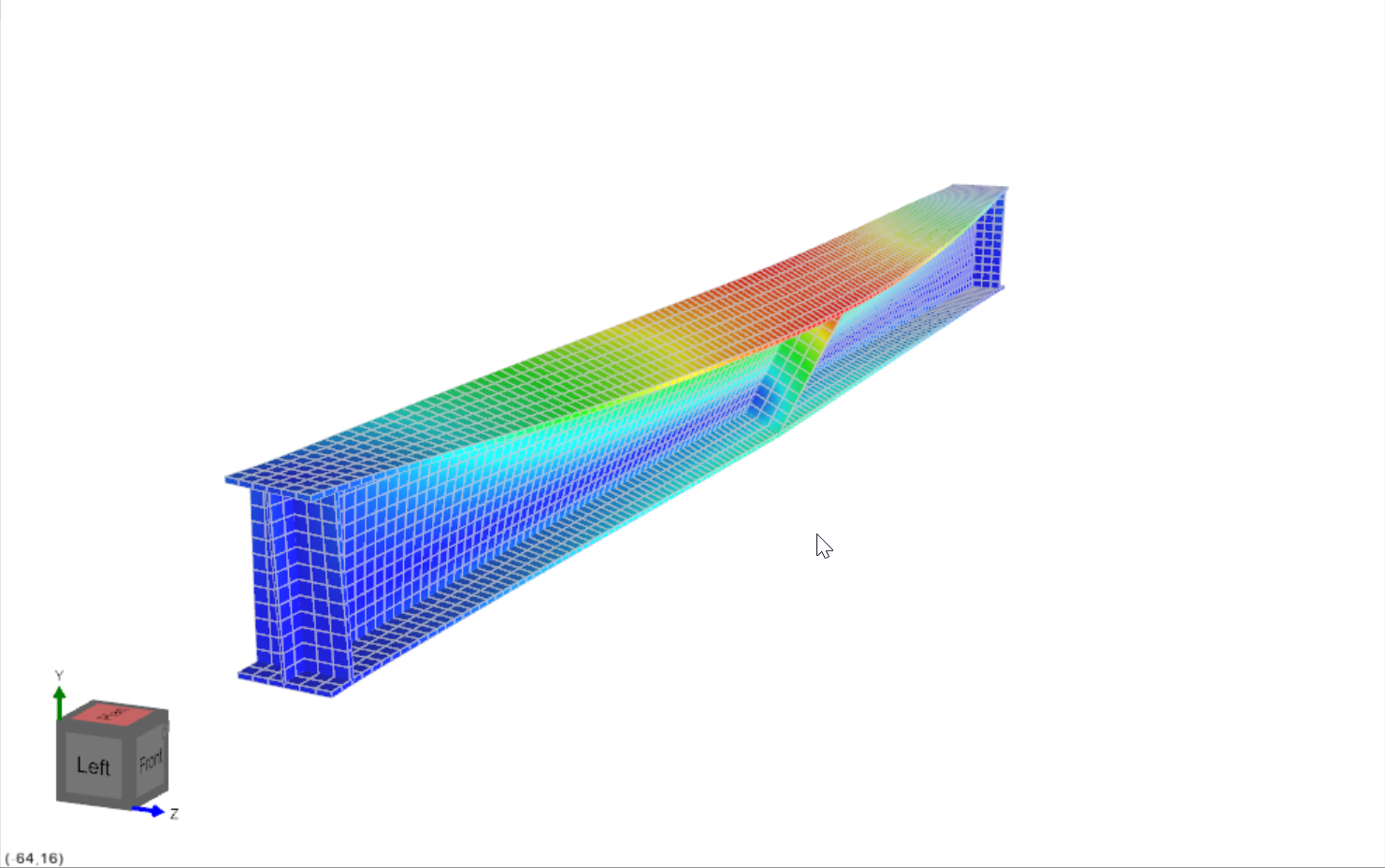
 Because each mode is normalized before scaling, the maximum deformation you enter is the true peak movement in the model for that mode, regardless of the raw magnitudes returned by the eigen solver. This makes the imperfection amplitude easy to control, for instance setting it to a fabrication tolerance or a fraction of the member length.
Result
A new model file is written with the displaced node positions, that is, the original geometry plus the combined, scaled mode shape offsets. All other structural and load data is carried across unchanged. Once the file has been saved, SPACE GASS asks whether you want to open it, so you can review the imperfect geometry or run a fresh analysis on it straight away.
 The displaced file is a normal SG model, so you can mesh it, load it, and run a fresh analysis on the imperfect geometry. Keep the original job as your clean reference model.