Cable Element Modelling
Cable members are frequently used in structural models to represent bracing, stay cables, and suspended elements. However, the way cable elements are handled differs significantly between the SG-X solver and the Paradise and Wavefront solvers. Understanding these differences is important for obtaining accurate results.
Cable Elements in Paradise and Wavefront Solvers
In the Paradise and Wavefront solvers, the cable element is a highly specialised dedicated element with its own accurate displacement theory. This means that even when small displacement theory is selected for the rest of the model, cable members are not affected: they use their own internal formulation that correctly captures the nonlinear behaviour of cables, including sag under self weight and tension stiffening effects.
This is a significant advantage because, under small displacement theory, conventional members assume that there has been no significant chord rotation. For example, a slender horizontal member supported at both ends with a midspan load will not develop any axial tension from the midspan deflection under small displacement theory. A cable element, however, will correctly capture this tension because of its specialised formulation.
Cable elements in Paradise and Wavefront also offer a practical advantage over tension only members. When multiple tension only members are used (e.g. for diagonal bracing), some members may be switched off and back on in successive iterations as the solver determines which members are in tension and which are in compression. This state of flux can sometimes cause the solution to diverge, particularly in models with large groups of tension only members. Cable members avoid this problem entirely: if a cable goes into compression, it simply sags, just as a real cable would.
Cable Elements in SG-X
When a user sets the member type to Cable in the member properties, SG-X internally subdivides each cable into a series of truss elements before the analysis begins.
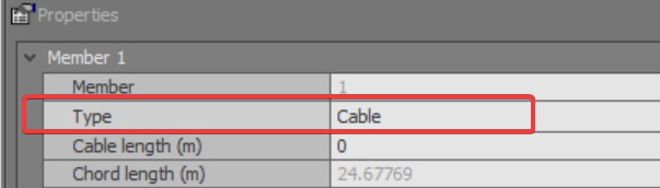
By default, each cable is subdivided into 20 truss elements internally. This default can be changed in the SG-X Advanced Settings dialog, under Split members into (Cable), shown earlier in Figure 2.
The appropriate subdivision count depends on the type of structure being modelled:
- Guyed masts and long cables. The default of 20 elements per cable should produce accurate results.
- Cable nets. The default of 20 elements per cable may be excessive and can lead to numerical instability. In such cases, setting the subdivision to 1 element per cable is often sufficient. Alternatively, users can model cable nets using truss elements directly to avoid potential instability.
Because the SG-X cable is composed of truss elements, it relies on the geometric non-linearity of the truss chain to capture the cable response. This means that nonlinear geometry should be enabled when modelling cables in SG-X to ensure accurate results.
Modelling Cables Directly with Truss Elements
Users also have the option of modelling cables directly as a series of truss elements, rather than using the cable member type. This approach gives the user full control over the number and spacing of elements along the cable.
A key advantage of modelling cables with truss elements is the ability to accurately capture dynamic mode shapes when running dynamic analyses (frequency, spectral, harmonic, or transient). Because each truss element has its own mass distributed along its length, the dynamic behaviour of the cable, including lateral vibration modes, is properly represented. This level of detail cannot be captured using the dedicated cable element in the Paradise or Wavefront solvers, where the cable is treated as a single element without internal degrees of freedom for dynamic analysis.
Buckling Analysis with Cable Elements in SG-X
When running a buckling analysis on a model that contains cable elements modelled as a series of truss elements (as in SG-X), special attention is required for slacked cables.
Consider, for example, a guyed mast structure with four cables. Under a particular load case, two cables may be in tension while the other two are slacked. Because the slacked cables are composed of truss elements with very low axial stiffness in their unloaded state, they will buckle very easily. As a result, the buckling analysis may return very low buckling load factors, even though the overall structure under the factored load is still stable.
This is a known consideration when using truss based cable elements in buckling analysis. A similar issue can arise in dynamic frequency analysis, where a small subset of the structure (such as slacked cables) vibrates at very low frequencies and pollutes the frequency spectrum with modes that are not relevant to the global structural behaviour.
The following approaches can be used to address this:
- Remove slacked cables manually. Identify cables that are slacked under the load case being analysed and remove them from the model before running the buckling analysis. This ensures that only structurally active elements participate in the buckling solution.
- Use stabilisation stiffness. Apply a minimum stiffness to the truss elements to prevent numerical instability of the slacked cables. The low buckling modes associated with the stabilised cables can then be filtered out, either by setting a window in the solver settings to ignore low critical values, or by reviewing the mode shapes and discarding the irrelevant modes manually. Care should be taken with this approach, as it can be difficult to distinguish between genuine low buckling modes and those caused by slacked cables.
With these known considerations in mind, we advise that if buckling analysis on a model containing cable elements is required, the Paradise or Wavefront solver should be used to avoid the issues described above.
A dedicated cable element, similar to the one available in the Paradise solver, is currently in development as part of the SG-X roadmap. In a future version of the SG-X solver, users will have two choices: model cables using a dedicated cable element or as a series of truss elements, depending on their analysis requirements.
Key Differences Summary
|
|
Paradise and Wavefront |
SG-X |
|
Element type |
Dedicated cable element |
Series of truss elements |
|
Displacement theory |
Own accurate formulation (independent of model setting) |
Relies on geometric nonlinearity of the truss chain |
|
Nonlinear geometry requirement |
Not required for cables (small displacement OK) |
Should be enabled for accurate result |
|
Compression handling |
Cable sags naturally |
Truss elements handle compression and buckling |
|
Subdivision |
Not applicable |
Default 20 elements (adjustable) |
|
Dynamic mode shapes of cables |
Not captured (single element, no internal DOFs) |
Accurately captured (using truss elements or cable subdivision) |
 For models that rely heavily on cable behaviour, users should be aware of these differences when switching between solvers. In Paradise and Wavefront, cables with small displacement theory selected will still produce accurate cable results. In SG-X, enabling nonlinear geometry is recommended to achieve comparable accuracy.