Stretch
The Stretch tool lets you stretch all or part of your model with two different options.

After selecting the nodes, members or plates to be stretched, right-click and select "Stretch" from the menu that appears. You should then pick an anchor point, plus two points that represent the ends of a vector through which the items are to be stretched.
Stretch: Option 1
Each selected item is then moved parallel to the stretch vector by an amount that is proportional to its distance from the anchor point. The distance by which a point is moved parallel to the stretch vector is given by:

where D is the distance moved, Lv is the length of the stretch vector, Dn is the distance from the node to the anchor point in the direction of the stretch vector, and Dv is the distance from the start of the stretch vector to the anchor point in the direction of the stretch vector.
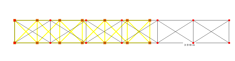
Stretch: Option 2
Each selected item is then moved parallel to the stretch vector by an amount that is proportional to its direct distance from the anchor point. The distance by which a point is moved parallel to the stretch vector is given by:
where D is the distance moved, Lv is the length of the stretch vector, Dn is the direct distance from the node to the anchor point (measured in a straight line, regardless of direction), and Dv is the distance from the start of the stretch vector to the anchor point in the direction of the stretch vector.
Because all nodes at the same direct distance from the anchor point move by the same amount, this option can be used to form conical or domed shapes from flat geometry. In the example below, the nodes of a flat circular grillage have been stretched vertically with the anchor point at its centre. The nodes move progressively more with increasing distance from the centre, transforming the flat plate into a cone.
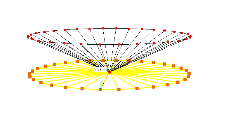
 Unlike Option 1, which moves all nodes in the same plane perpendicular to the stretch vector by the same amount making it suitable for uniformly elongating or shortening part of a model, Option 2 moves all nodes at the same direct distance from the anchor point by the same amount, making it suitable for forming conical or domed shapes from flat geometry.
Don't forget that when drawing in the renderer, you can attach to other nodes or members, or you can "lock on" to a node or member and then align with an orthogonal line or an extension line from the "locked on" node or member. You can also align with one of the three global axes. For more information, refer to Attachment and alignment methods. Remember also that when drawing, you can use the mouse or you can simply type in the coordinates of the desired point(s). For more information, refer to "Positioning points using the keyboard".