Portal frame purlins and girts
Purlins and girts are not actually generated in the model, but the purlin and girt sizes you specify are used to determine the frame dimensions based on the distance from the sheeting line to the column and rafter flanges. The purlin, girt and fly brace positions are also used to determine the flange restraint positions and types in the steel design data.
For your convenience, the purlin and girt sizes can also be specified in the Sections tab.
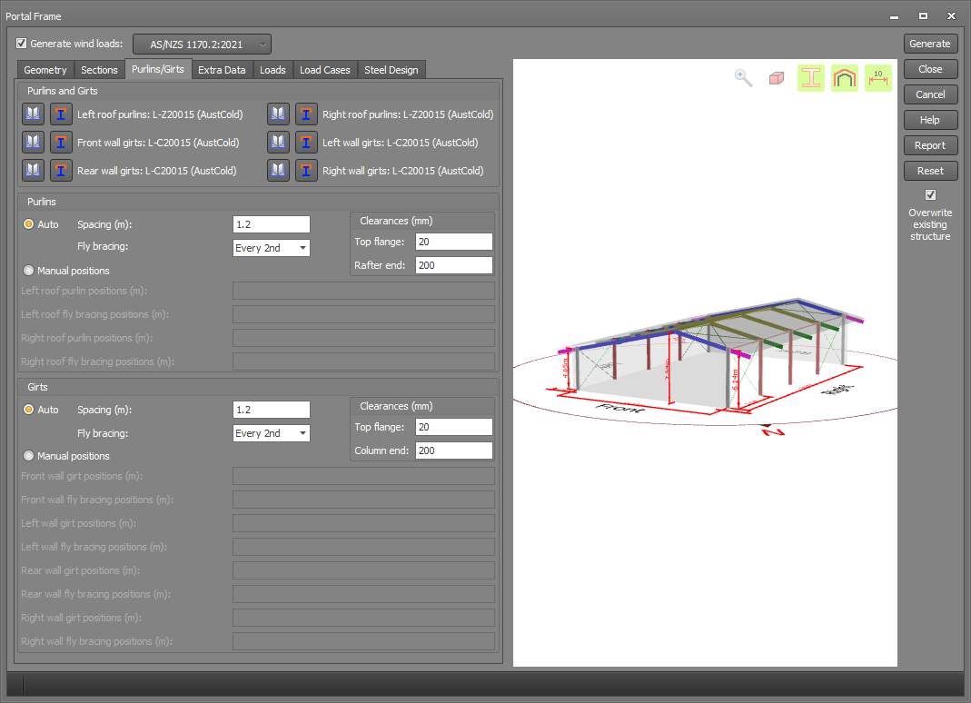
When using the "Auto" options below, you can specify the purlin or girt spacing, fly brace positions and clearances. The top flange clearances represent the gap between the purlin or girt and the rafter or column flange to which they are attached. The rafter or column end clearance is the distance from the end of the rafter or column to the first purlin or girt. Purlins are positioned starting from the outside and working inwards to the ridge, except for monoslope roofs where they start from the left. Girts are positioned starting from the bottom and working upwards.
As an alternative, "Manual positions" allow you specify the exact locations of the purlins, girts and fly braces. Each positions field can contain a single value or a list of values separated by commas. You can also use the "@" symbol to represent groups of equally spaced purlins or girts inside a list. For example, a list of "0.9,5@1.2,7.9" could be used to represent purlins located at 0.9, 2.1, 3.3, 4.5, 5.7, 6.9 and 7.9 along a rafter. Another possibly more convenient way of specifying the same thing could be to use a list of "0.9,5@1.2,1@1.0".
If a fly brace is approximately lined up with a roof tie (within 100mm) but the roof tie has not been continued to the particular frame containing the fly brace, SPACE GASS adds a node with a restraint normal to the plane of the frame. This is to model the restraining effect of the fly brace which is assumed to transmit the restraining force through the purlin to the roof tie and into the roof bracing system.