Member design results
The AS4100 member design module running in checking mode was then initiated and the results are shown in the following computer printout.
The rafters are satisfactory with load factors of 1.15 and 1.05. The 530 UB 92.4 columns have also passed with load factors of 1.28 on both sides.
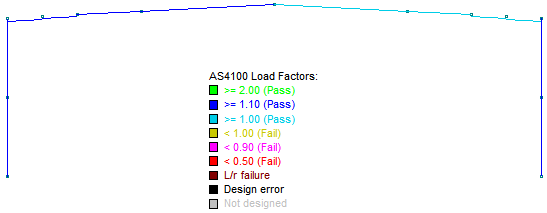
The results of a steel member design or check can be shown graphically as in the above diagram. The member colors matched to the legend show that the columns and left rafter have passed with load factors greater than 1.10, while the right rafter has passed with a load factor greater than 1.00.
In this example, because the approximate sizes of the columns and rafters were known in advance, it was appropriate to simply run a steel member check rather than a design. If the steel module had been run in design mode instead, the column members may have been selected as slightly less than 530 UB 92.4 because of their load factors being 1.28 and quite a bit greater than 1.00.
Thus, if you know that your initial analysis member sizes are close to the final design sizes, the recommended procedure is to run a steel member check first rather than a design. If the check results show that the analysis member sizes are almost correct then it is a simple matter to manually change some of the analysis member sizes and then do a final check to verify that they are correct.
Alternatively, if your analysis member sizes have not been chosen carefully, you should run a steel member design and then choose "Update analysis member sizes" from the Steel menu (see also Updating analysis member sizes) to update the analysis data and bring it in line with the design data. You should then iterate the analysis-design procedure until the design member sizes agree with the analysis member sizes.