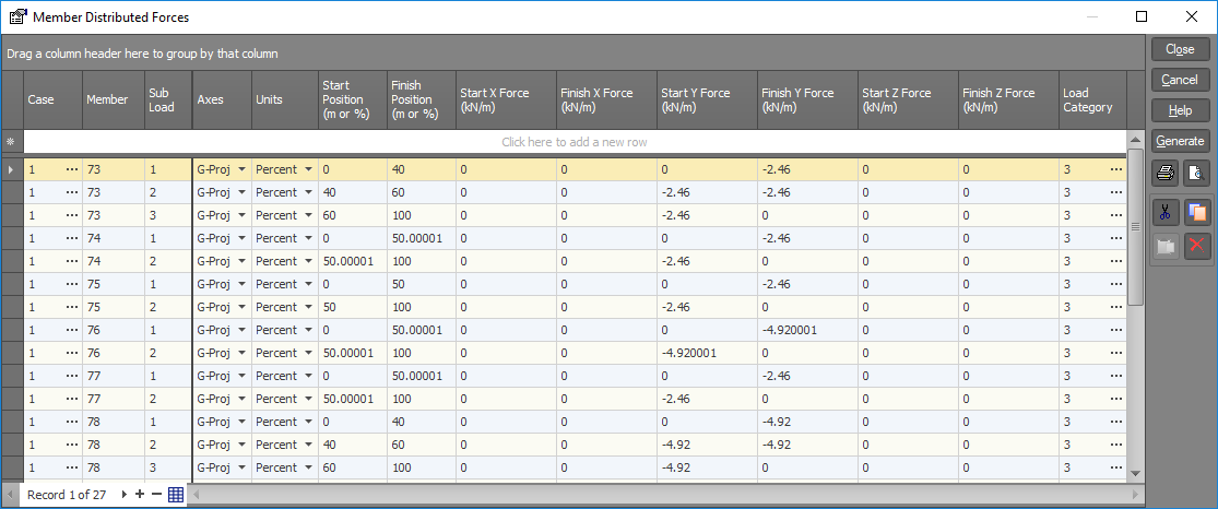
Member distributed force data
Member distributed forces can be input in the local or global axes systems and can act along any of the three axis directions.
Distributed forces may start and finish at any point along the member length and may vary in intensity from start to finish. Thus, it is possible to apply uniform, trapezoidal, or triangular distributed loads.
Member distributed forces may be applied in any load case and may be combined with other load types within the same load case.
! IMPORTANT NOTE !
For "Local" or "Global Inclined" loads, the total load is equal to the load per unit length multiplied by the actual distance between the load start and finish positions. For "Global Projected" loads, the total load is equal to the load per unit length multiplied by the projected distance between the load start and finish positions.
! IMPORTANT NOTE !
For cable members, distributed forces must be uniform and extend over the entire length of the cable. For "Global Inclined" UDLs applied to cable members, the total load is equal to the load per unit length multiplied by the unstrained cable length (which may not be equal to the distance between the cable’s end nodes). For "Global Projected" UDLs applied to cable members, the total load is equal to the load per unit length multiplied by the projected distance between the cable’s end nodes.
Case
Load case to contain distributed member forces.
Member
Member to be loaded.
Sub load
This allows you to reference multiple distributed loads on a member in the same load case. Each load is given a sub load number (different to a load case number). For example two distributed loads applied to a member within the same load case would have sub load numbers of 1 and 2 respectively. Unless there are multiple loads applied to a single member within the same load case, the sub load number should be 1.
Axes
Axes system in which loads are referenced. There are two global axes systems which may be used. When the axes are designated as "Global projected" the load acts over the projected length of the member, while a "Global inclined" load acts over the actual length of the member.
|
Choices are: |
Local, |
|
|
Global projected, |
|
|
Global inclined. |
Units
Units system in which load positions are referenced.
|
Choices are: |
Actual, |
|
|
Percentage. |
Start and finish positions
The load start and finish positions are taken relative to node A. Depending on the "Units system" selected, this distance may be expressed as an absolute length or percentage of the member length. Thus, a member 600mm long with a load that extends from the 150mm mark to the end could have the load start position specified as 150mm or as 25%, and the load finish position specified as 600mm or as 100%. The finish position must always be greater than start.
X, Y and Z start and finish forces
Start and finish member distributed forces.
Load category
The load category column lets you specify which load categories the loads will go into. For more information refer to "Load categories".
See also Member distributed forces text.
See also Datasheet Input.
See also Member distributed forces.
See also View diagrams.
See also Cable members.