Member distributed torsion data
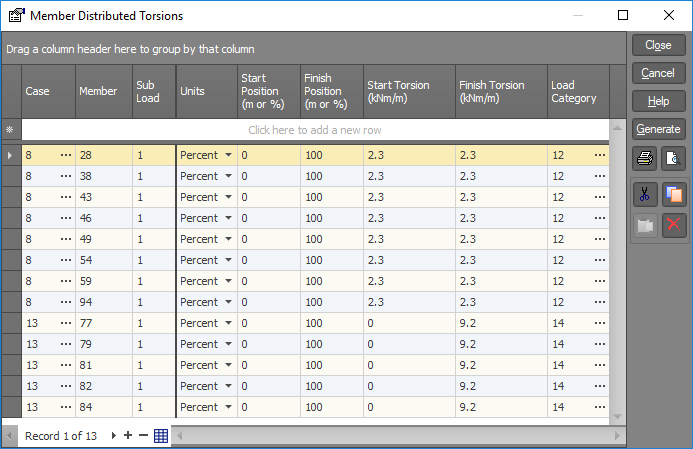
Member distributed torsion loads are similar to member distributed forces except they may only be applied about the local x-axis. The load intensity may be varied between the start and finish positions. Member distributed torsions may be applied in any load case and may be combined with other load types within the same load case.
Case
Load case to contain distributed member torsions.
Member
Member to be loaded.
Sub load
This allows you to reference multiple distributed torsions on a member in the same load case. Each load is given a sub load number (different to a load case number). For example two distributed torsions applied to a member within the same load case would have sub load numbers of 1 and 2 respectively. Unless there are multiple loads applied to a single member within the same load case, the sub load number should be 1.
Units
Units system in which load positions are referenced.
|
Choices are: |
Actual, |
|
|
Percentage. |
Start and finish positions
The load start and finish positions are taken relative to node A. Depending on the "Units system" selected, this distance may be expressed as an absolute length or percentage of the member length. Thus, a member 600mm long with a load that extends from the 150mm mark to the end could have the load start position specified as 150mm or as 25%, and the load finish position specified as 600mm or as 100%. The finish position must always be greater than start.
Start and finish torsion load
Start and finish member distributed torsion load.
Load category
The load category column lets you specify which load categories the loads will go into. For more information refer to "Load categories".
See also Member distributed torsions text.
See also Datasheet Input.
See also Member distributed torsions.
See also View diagrams.