Creating and editing connections
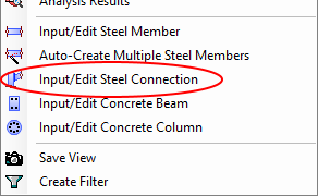
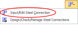
In order to define a steel connection, it is simply a matter of selecting the members to be connected, clicking the right mouse button and then selecting "Input/Edit Steel Connection" from the menu that appears or by clicking the button in the top toolbar and then selecting "Input/Edit Steel Connection".
Note that most connections require two members to be selected, however for base plates, single member stiff seats and some of the tubular connections, only one member needs to be selected.
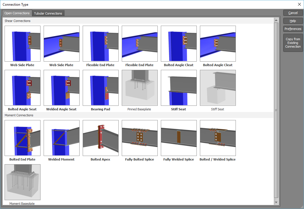
You must then select the type of connection you want from the following table. Connections that are invalid for the number of members you selected will be disabled in the table.
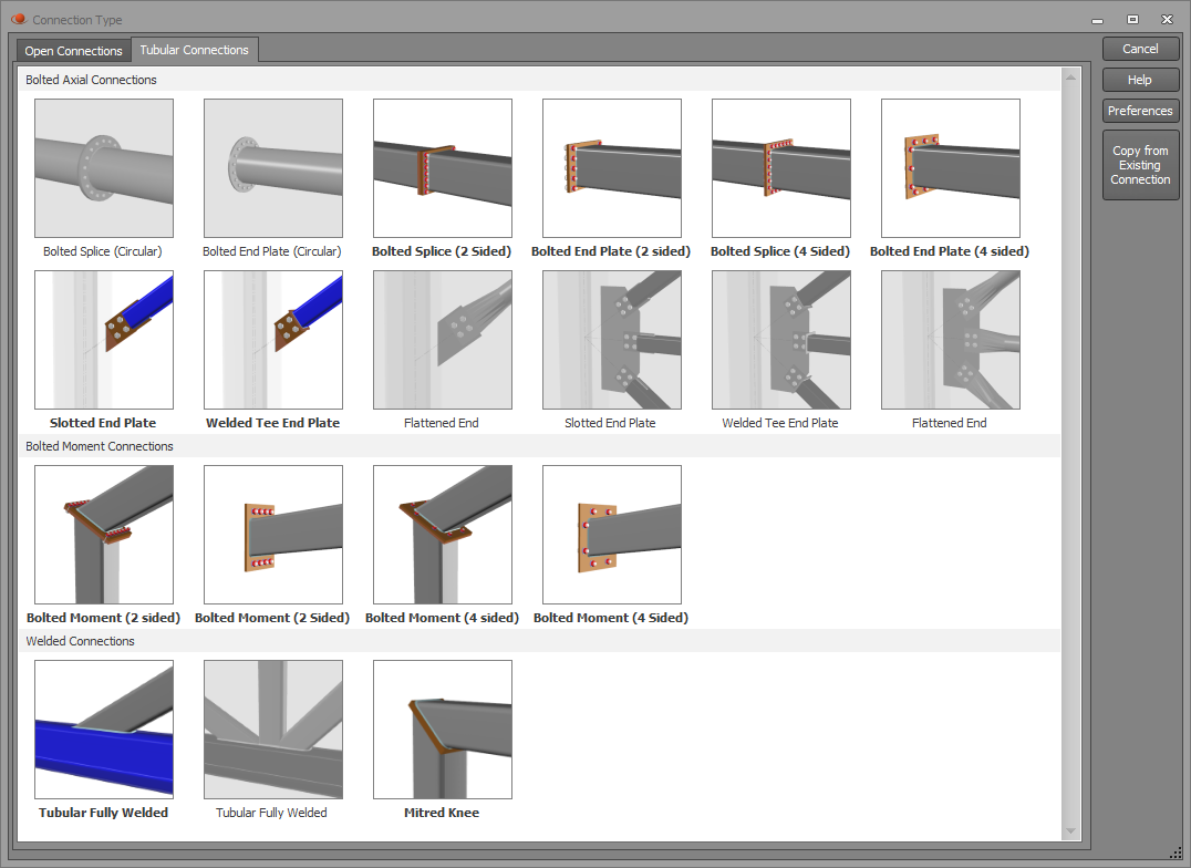
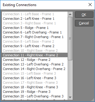
Alternatively, if you wish to make it the same as a connection that has already been created, you can click the "Copy from Existing Connection" button and then select from a list of the existing connections.

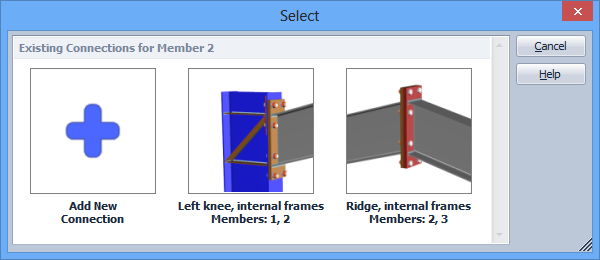
Note that if your model already contains connections, you can see which ones are attached to a particular member by selecting that member, clicking the right mouse button, choosing "Steel Connection Design" from the menu and, if the selected member already has connections they will be displayed in the following table. You can then click "Add New Connection" to create a new connection for that member or edit one of its existing ones.
Regardless of which of the above methods you used, the connection is then designed (or checked if you have copied from an existing connection) and the results are presented in the connection editor shown below.
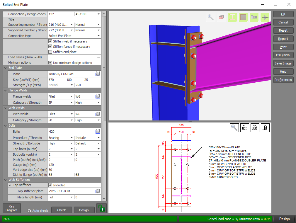
From there, you can examine the connection, click the Ok button to save and exit if you happy with it, or make changes to customize it to your exact requirements.
Connection viewer
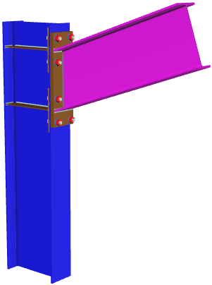
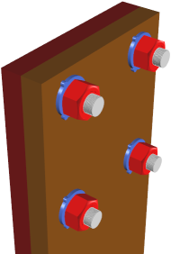
The connection viewer in the right-hand side of the editor gives you a realistic 3D rendered view of the connection.
You can zoom, pan and rotate the image using the mouse in the normal way.

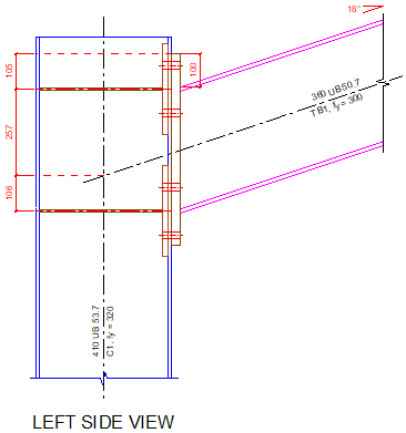
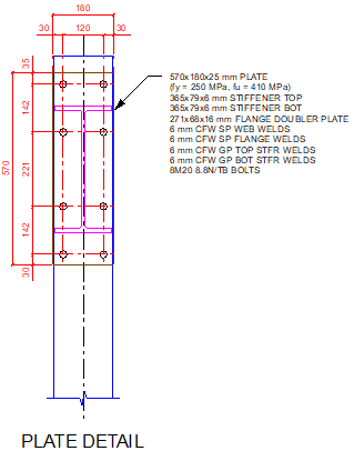
Or you can click the buttons in the connection viewer windows to do a "Zoom fit", display annotated 2D elevations or switch back to the 3D rendered image.

Input/edit fields
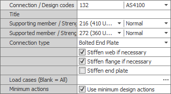
In order to edit the connection, you can change any of the data fields in the left-hand side panel. Some of the key input fields are as follows:
Connection number
This is the unique identification number of each connection. By default it is set to the node number at the connection, however if that number is already taken by another connection then it uses the next available number. You can manually set it to comply with whatever numbering scheme you prefer.
Design code
Currently only AS4100 is available.
Title
You can specify an optional title that helps you to identify each connection. If you leave it blank then the connection is referred to by its number and connection type.
Supporting and supported member
These are the members that are connected to each other. When you first create the connection, SPACE GASS automatically determines which member is the supporting member and which one is supported, however if you wish to swap them you can do so in this form. You can also set the strength for each of the members.
Connection type
If you wish to change the connection type to one of a similar category then you can do so with this field. For example, you could change a bolted end plate to a welded moment connection or a web side plate to a flexible end plate, however you couldn't change a bolted end plate to a web side plate because they are in different categories. If you wish to change to a connection of a different category then you must click the "Change Connection Type" button on the right side of the editor and then re-select from the table of connection types.
Stiffen web/flange if necessary
Ticking these options means that web or flange stiffeners will be included in a design only if required. If you untick these options and stiffeners are required then the connection will fail.
Stiffen end plate
If you tick this option then the end plate will always be stiffened and this may result in a thinner end plate than would otherwise be required.
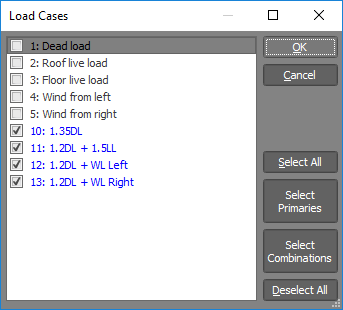
Load cases
If you want to consider all load cases then this field should be left blank, otherwise you should type in your desired list of load cases (separated by commas or dashes). Alternatively, you can click the "..." button to the right of the input field and then select the load cases you want from the list that appears as shown below.
Minimum design actions
In order to ensure that each connection is well proportioned and robust, especially when the analysis design actions are quite low, the code nominates minimum design actions that should be complied with. Normally you would leave this option ticked, however you can turn it off if required.
Note that if you haven't purchased the steel connection design module, you can still run it in a free trial mode that limits you to using minimum design actions. When running in this mode, any load cases you type into the "Load cases" field are ignored and you can't turn off the "Minimum design actions" option.
Haunches, plates, welds, bolts, stiffeners and cleats
The remainder of the input fields involving haunches, plates, bolts, stiffeners and cleats are connection dependent. You can change any of them to configure a connection to exactly what you want. Any fields with a  library button give you access to the relevant library for the type of data being input.
Designing and checking
When you first create a connection, it is automatically designed and the results are presented in the connection editor. You can either accept it in that state or you can proceed to make changes and then have it checked.
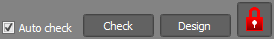
If you change one of the input fields that could be overwritten by a design, the connection becomes locked. This is a safety feature that guards against you inadvertently clicking the "Design" button and losing your changes. If you really want to design the connection after making changes that lock it then you must first click the padlock button to unlock it.
Note that some input fields do not cause the connection to be locked, as they are input fields only and are not overwritten when you perform a design. Examples of these are bolt strength, bolting procedure, weld strength, etc.
Locking a connection
If you wish to prevent any further changes to a connection that isn't already locked, you can lock it by clicking the padlock button. This will stop any of the components of the connection from being changed if a batch design is performed via the connection manager.

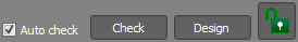
Auto check
If the "Auto check" option is ticked then a check is automatically done as soon as you make a change to any component of your connection. If it is unticked then no checking is done until you click the "Check" button.
Status bar
The status bar at the bottom of the editor indicates whether the connection has passed, failed or passed with a warning. It includes the critical load case, the utilization ratio and a brief explanation of the failure mode or warning message. A green line indicates it has passed, red indicates failure and yellow is for a pass with a warning message. All of these colors can be changed via the "Preferences" button.


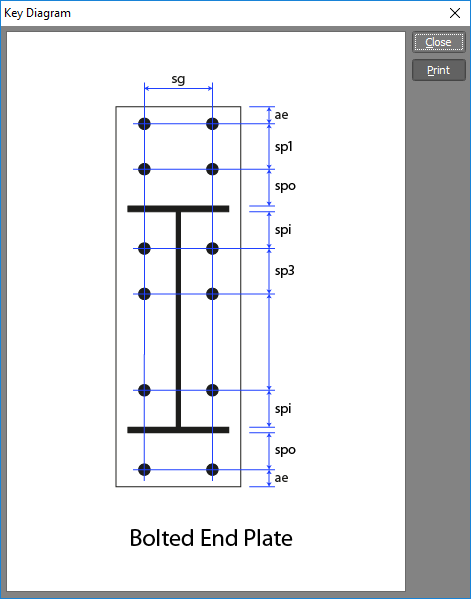
Key diagrams
The symbols used in the connection input fields match the ASI design guides, however some of the commonly used ones are also shown in key diagrams that you can view by clicking the "Key Diagram" button.

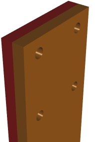
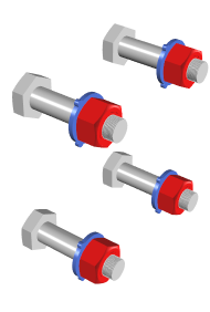
Hiding components
If you wish to examine components of the connection that may be difficult to see or partially obscured, you can turn on or off the members, plates, bolts or welds using the buttons shown below. They are all on by default.

Reset
If you wish to undo all the changes made to a connection (except for its connection number and title), you can click the "Reset" button. This will put it back to its default state, the same as if you deleted the connection and then re-created it.
Reports
A single report (including a graphical representation of the connection) for the connection currently in the editor can be obtained by clicking the "Report" button. Alternatively, you can generate text reports for multiple connections via the report panel of the connection manager or via the normal SPACE GASS report generator in the non-renderer window. Refer to "Connection reports" for more information.
Exporting
You can export the current connection to a CAD system via the "DXF" or "DWG" buttons. It can then be imported into AutoCAD or any other program that supports those formats.
Preferences
The "Preferences" button lets you change various connection parameters and colors. For more information refer to "Connection preferences".
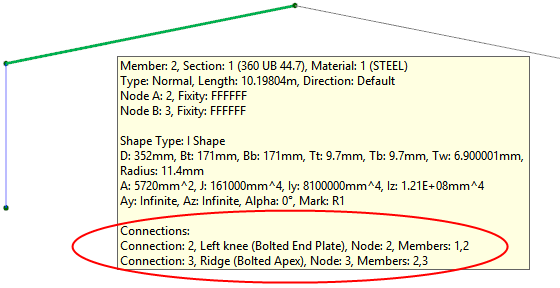
Infotips
Once you have created some connections, you can hover over a node or member in your model to see which connections are attached to it.