Member groups
In a typical structure, the actual beams, columns, struts, ties, etc. are modelled in SPACE GASS as members connected together at nodes. Sometimes, however it is convenient and often necessary for members to have nodes placed at intermediate positions along them so that they are subdivided into smaller members. This can occur when another member intersects a member at an intermediate point or when a node is simply placed at an intermediate point so that deflections, forces and moments are calculated at that point during the analysis.
Quite often the placement of intermediate nodes along a member is done purely for frame analysis modelling purposes rather than due to an actual discontinuity or connection in the real structure. For this reason, SPACE GASS allows you to group frame analysis members together and design them as though they are a single entity (as they are in the real structure). In the remainder of this manual a "design group" represents an actual member in the real structure which consists of one or more frame analysis members grouped together end-to-end.
![]() Note that in the following discussion, members in a group can be listed in either direction. For example, "1,3,8,5" and "5,8,3,1" are both suitable. The direction can, however affect the definition of the top flange (see also Flange restraints).
Note that in the following discussion, members in a group can be listed in either direction. For example, "1,3,8,5" and "5,8,3,1" are both suitable. The direction can, however affect the definition of the top flange (see also Flange restraints).
Consider, for example, a simply supported beam with a node at each end which is subjected to an axial compressive force and a uniformly distributed dead load. When analysed, the deflected shape and bending moment distribution along its length is calculated by SPACE GASS. If the structural adequacy of this member is then checked against one of the design codes, various factors are calculated based on the deflected shape and the bending moment distribution. These factors are then used in the calculations to determine if the member is adequate or not.
If the same beam is modelled with a third node at midspan, you would still get the same deflected shape and bending moment distribution, however unless you were able to group the two halves of the beam together and design them as though they were a single member you would get a completely different design result. This is because the factors and the combined actions moments and axial forces would be based on the deflection and moment distributions for only half of the beam rather than its full length.
![]() If a member has been subdivided into smaller members in the analysis model, it is important that these sub-members are grouped together in the design model.
If a member has been subdivided into smaller members in the analysis model, it is important that these sub-members are grouped together in the design model.
The rules for deciding whether or not a run of frame analysis members should be grouped into a design group are as follows.
- Each member in a design group must be rigidly connected to each other end-to-end, they must lie generally in a straight line, and they must have the same section properties.
- The length of a design group should not be less than the major axis span.
- A design group must be long enough to include all of the flange restraints that affect its bending effective lengths. Furthermore, under no circumstances should the design group length be less than the unrestrained lengths of the top and bottom flanges. This rule is not applicable if the bending effective lengths are specified directly rather than being calculated.
- Each end of a design group should coincide with the physical end of a member or a significant change in direction of a member, or a support point for a member. It shouldn’t normally extend past a support or past an intersecting member that effectively acts as a support. "Support" refers to a support for the major axis span.
![]() If it is not possible for all of the above rules to be satisfied then you should not use SPACE GASS to design the steel members involved.
If it is not possible for all of the above rules to be satisfied then you should not use SPACE GASS to design the steel members involved.
Consider the following examples, indicating how members in typical frames can be grouped together.

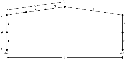
Member grouping for gable portal
|
Group 1: |
1,2 |
|
Group 2: |
3,4,5 |
|
Group 3: |
6 |
|
Group 4: |
7,8 |

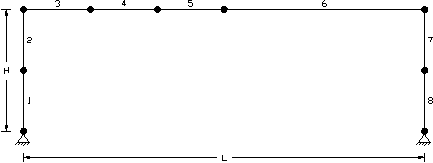
Member grouping for flat portal
|
Group 1: |
1,2 |
|
Group 2: |
3,4,5,6 |
|
Group 3: |
7,8 |

Member grouping for truss
|
Group 1: |
2,6,10,14,18,22 |
|
Group 2: |
4,8,12,16,20,24 |
|
Group 3: |
1 |
|
Group 4: |
3 |
(Some of the non-critical members have not been grouped)
! IMPORTANT NOTE !
The above grouping assumes that local bending of the chords between panel points is insignificant compared with overall bending between the end supports (ie. the panel points are not really acting as support points for the chords). If the chords were effectively spanning L/6 instead of L then the chord members could not be grouped.

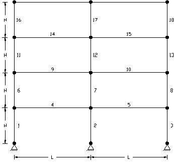
Member grouping for multi-storey frame
|
Group 1: |
1 |
|
Group 2: |
2 |
|
Group 3: |
3 |
|
Group 4: |
4 |
|
Group 5: |
5 |
|
Group n: |
n |
|
etc... |
|
No grouping of multiple members can occur in this case because each member acts as a single span. The horizontal beams act as supports for the columns at each floor and the columns act as supports for the beams.
Note that, if there was no significant axial forces in the beams such that they were not acting as supports for the columns then the columns could be grouped into one design group from bottom to top. This would not, however be a common situation.
![]()
Member grouping for continuous beam
|
Group 1: |
1,2,3,4 |
|
Group 2: |
5,6 |