The SPACE GASS reinforced concrete beam design module lets you design or check any of the concrete beams in your structural model.
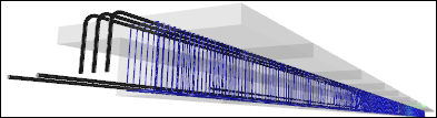
Operating the module simply involves you selecting the members that form a beam and then selecting the concrete beam design module. The beam is immediately designed and presented to you as a fully rendered 3D image and cross section in the beam editor. From there you can examine it in more detail by zooming, panning or rotating, or you can change any of the design parameters or reinforcement to meet your exact requirements.
Each time you make a change, the beam is automatically re-checked or designed and the 3D image and cross section is updated so that you can see exactly what is happening as you go.

Beam design video
Moment and Shear Diagrams
Moment and shear diagrams show the envelopes for your ultimate, serviceability and sustained load cases.
The green lines above and below the bending moment envelope represent the bending capacity of the beam and give a very good indication of how efficient your beam design is. The closer they track the bending moment envelope the more efficient your beam design is.

After a design, the critical zone is selected and shown shaded in the diagrams. The image in the cross section panel also reflects the currently selected zone. You can change to any other zone (and matching cross section) by simply clicking it in the moment, shear or deflection diagram.

You can hover the mouse cursor over any part of a diagram to show the underlying values at the cursor's location.

Deflections
The deflections tab displays the elastic, short term, long term and total deflections based on the "Serviceability" and "Sustained" load cases specified. The elastic deflections match the deflections from the SPACE GASS analysis and are based on the gross moment of inertia (Ig), the short term deflections are based on the cracked moment of inertia (Iefs) and the long term deflections are based on the moment of inertia adjusted for creep (Iefl). The total deflections are the sum of the short term and long term deflections.

Drawings
The cross section panel shows the cross section and reinforcement for the currently selected zone, while the "2D View" tab in the beam view panel shows the longitudinal section for the entire beam.

Fully detailed cross section and longitudinal section drawings can be exported to DXF or DWG files for use in your CAD system.

Zones
By default there are five zones per span, consisting of a zone at the supports at each end of the span plus three zones in the span. These can be changed by you if required.
You can change the currently selected zone via the data panel at the left or by clicking in the beam view panel at the top or by clicking in the moment, shear or deflection diagrams.
During a design, SPACE GASS calculates the reinforcement for each zone and then optimizes it so that continuity of bars along the entire beam is maintained. Bars are terminated in the zones in which they are not required.
Moment Redistribution
Moment redistribution allows you to reduce the bending moments at the supports with a resulting increase in the span moments. It is generally only applied to the internal supports of statically indeterminate beams, but you can also choose to redistribute the moments at the beam's end supports if appropriate.

When moment redistribution is activated you must choose the amount of redistribution and specify whether that amount applies at the support centerlines or at the faces of the supports. During moment redistribution the shear forces are also adjusted to maintain static equilibrium.
Bar Anchorage
Bars can be left straight at the ends of the beam or they can be hooked or cogged.
Development Lengths
Development lengths are calculated automatically based on the bar size, bar type, end anchorage, concrete properties and bar stress. They are included in the reports and are displayed in the beam view panel.
Output Panel
A handy output panel lets you see a summary of the results and calculations for the currently selected zone. Many of the values in this panel are also included in the output reports.

Data Panel
The data panel on the left of the beam editor lets you control the load cases to be considered, shear checks, minimum design actions, moment magnifiers, effective lengths, reinforcement percentages, bar sizes and design priorities.

Design mode
When performing a design, the module evaluates many solutions (sometimes hundreds), discards the impractical ones and then sorts the rest according to the "Design Priority" setting that you have selected. For example, if you have selected "Minimum bars" then it will put the solution that has the minimum number of bars first and present that as the optimal solution. "Minimum steel" gives the most efficient design in terms of total area of steel, however it usually results in many different bar sizes throughout the beam and so is often impractical. "Minimum layers" or "Minimum bars" give the best results in most circumstances.
If you have the "Auto" option at the bottom of the form ticked and the beam is not locked (ie. the padlock button at the bottom is green) then whenever you make a change to any of the design parameters, the design is repeated and the reinforcement updated. Of course you can untick the "Auto" option if you don't want this to happen automatically.
During a design, the module attempts to continue some bars along the entire beam, and terminates other bars in the zones that don't require them. Development lengths are calculated and applied wherever bars are terminated.

Check mode
If you manually change any of the bar counts or sizes in this panel then the beam will become locked (ie. the padlock button at the bottom will become red) and any further changes you make to the design parameters will simply cause the reinforcement to be checked rather than be changed.
Any changes you make to the reinforcement in a zone can be copied to other zones for continuity along the beam. You can also terminate bars as you move along the beam to allow for the shape of the bending moment diagram.

Management Form
The concrete management form lets you manage all your reinforced concrete beams and columns in one convenient location. You can re-design or re-check them in batch mode, view the results, generate reports or open any member in the beam or column editor.

Status Bar
The status bar at the bottom of the editor or management form lets you see at a glance whether the beam has passed, failed or passed with a warning. It includes the critical load case, the critical zone, the utilization ratio and a brief explanation of the failure mode or warning message. A green line indicates it has passed, red indicates failure and yellow is for a pass with a warning message.


Reports
Reports contain all of the key information for the beam design, including drawings of the critical cross sections, a complete reinforcement specification, development lengths, capacities for each zone along the beam, and span deflections. More detailed reports also include a full set of calculations for each zone.

Preferences
You can click the "Preferences" button to open the concrete beam preferences form and then change the defaults for various concrete parameters such as the default bar library, spacings, cover, size ranges, fire rating, zones per span, bar anchorage, deflection settings, colors and other options.

