Supported Element Types
SG-X supports all element types and modelling features available in SPACE GASS, ensuring full backward compatibility with existing models. The following elements and features are fully supported.
Standard Beam and Frame Elements
General purpose beam and frame members with axial, transverse shear, bending, and torsion stiffness, based on Reissner-Timoshenko beam theory. Each element has 6 degrees of freedom per node (3 translations and 3 rotations).
In SG-X, the beam element formulation differs depending on the analysis type.
- Linear analysis. A beam element with two nodes is used. The element employs the small strain and small deflection form of Reissner-Timoshenko theory, and for straight uniform beams it provides exact displacements and exact resultant stresses.
- Non-linear analysis. A beam element with four nodes (the EDGE4 element) is used, as described below.
For a nonlinear static analysis, SG-X uses a four node cubic beam element. The two end nodes remain the nodes you define; before the analysis begins, the solver automatically inserts two interior nodes along each member, at the one third and two third points of its length.
These interior nodes are created and managed entirely by the solver and belong to that element alone, so from the user’s perspective every beam is still defined by just its two end nodes, and any end releases or hinges act on the end nodes exactly as before.
The cubic interpolation captures curvature and second order (p-delta) behaviour far more accurately per element than the two node linear element.
The underlying formulation is a Reissner-Timoshenko beam based on the Green-Lagrange strain measure, resisting axial force, transverse shear, torsion, and bending, with six degrees of freedom per node.
Geometric nonlinearity is carried by a geometric stiffness matrix built from the current internal forces of the element, which accounts for stress stiffening and the geometric response of the member.
Small and Large Displacement Theory
When SG-X is the active solver, a Theory option is available with two settings, Small and Large, which control how the member deformation is treated. A third setting, Finite, is reserved for a future release and is disabled for SG-X. Both settings share the same four node element and the same Green-Lagrange strain measure, and differ only in how displacements and rotations are handled:
- Small displacement theory (default). Strains follow the Green-Lagrange measure, but displacements and rotations are assumed to remain small. The geometric stiffness is formed from the current internal forces but is not recomputed for the deformed shape, so equilibrium is effectively written on the original geometry. This captures stress stiffening and second order (p-delta) effects efficiently and is appropriate when deflections and rotations stay modest.
- Large displacement theory. The beam uses the fully geometrically nonlinear formulation: both the tangent and geometric stiffness are updated as nonlinear functions of the current displacements and rotations, and equilibrium is formed on the deformed geometry at every load step (updated member orientation and length, exact rotation matrix). This is required for genuinely large deflection and large rotation problems such as snap through, post buckling, and cable or very slender structures, and it generally converges more reliably than the small displacement model once deformations become large.

 A buckling analysis always uses small displacement theory internally, regardless of the dialog selection, because buckling runs on the two node element, where the large displacement beam formulation is not appropriate.
Tension-Only and Compression-Only Members
- Tension-only members can only resist tensile forces and are commonly used for modelling bracing rods and cables. In the Paradise and Wavefront solvers, tension only members cannot carry compression but can still carry bending and shear in addition to tension. In SG-X, tension only members carry tension only: they cannot resist compression, bending, or shear.
- Compression-only members can only resist compressive forces. In the Paradise and Wavefront solvers, compression only members cannot carry tension but can still carry bending and shear in addition to compression. In SG-X, compression only members carry compression only: they cannot resist tension, bending, or shear.
In SG-X, tension only and compression only members cannot carry distributed member loads (such as UDLs or distributed moments): the solver reports a validation error if one is applied. Because the element is axial only, a concentrated load applied along the member cannot produce bending or shear either, so loads should be applied at the member end nodes instead. The exception is self weight, which is calculated and divided equally as point loads applied at the two end nodes.
Cable Members
Cable members are specialised elements for modelling cables in static and buckling analysis. In the Paradise and Wavefront solvers, the cable element is a highly specialised element with a catenary shape formulation, where internal forces are calculated in post processing.
In SG-X, cable elements are modelled as a series of truss elements. By default, SG-X subdivides each cable into 20 elements. This default can be changed via the SG-X Advanced settings. The appropriate number of subdivisions depends on the type of structure being modelled; detailed guidance, together with a full comparison against the cable formulation in the Paradise and Wavefront solvers, is given in SG-X Cable Element Modelling.
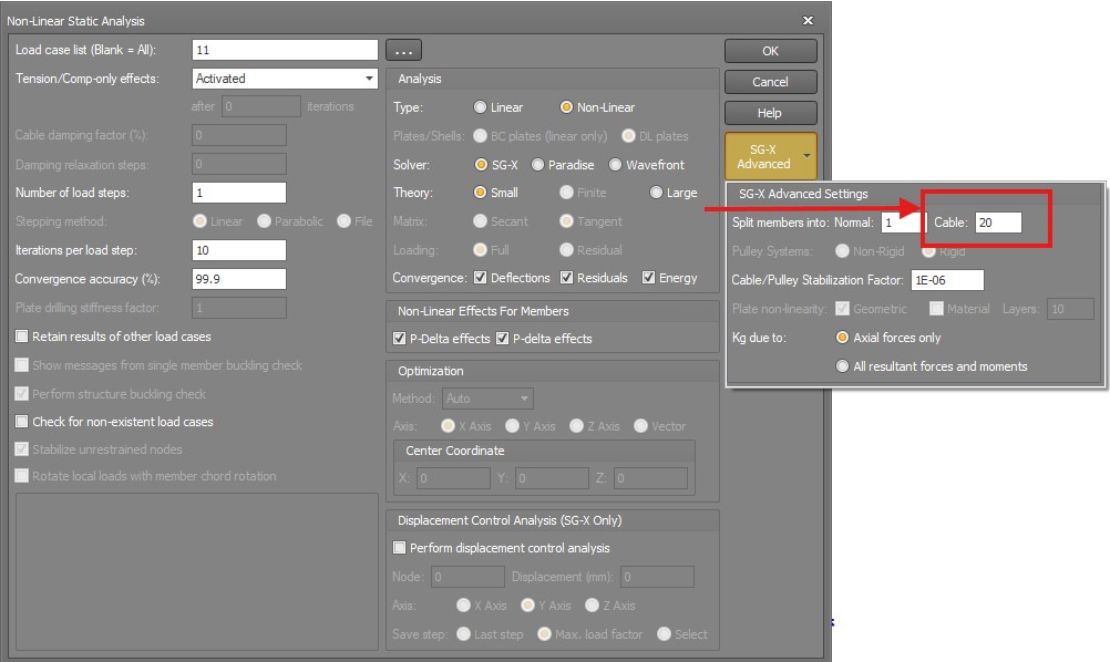
Plate and Shell Elements
Plate and shell elements are two dimensional elements for modelling slabs, walls, and other planar structural components, with support for nonlinear static analysis and buckling. In the Paradise and Wavefront solvers, plate and shell elements support nonlinear geometry only. SG-X extends this capability by supporting both nonlinear geometry and nonlinear material behaviour.
SG-X employs advanced shell element formulations to ensure accuracy and robustness:
- Three node triangle elements. These use a special assumed strain field to prevent transverse shear locking (T3 ANS formulation).
- Four node quadrilateral elements. These incorporate special treatments for transverse shear locking, in plane membrane behaviour improvement, and membrane locking alleviation for warped faces (Improved MITC4+ formulation).
Other Supported Features
- Elastic supports. Spring supports with defined translational and rotational stiffnesses.
- Master and slave constraints. Constraint relationships between nodes for modelling rigid links and diaphragm behaviour.
- Member offsets. Eccentric connections between members and nodes.