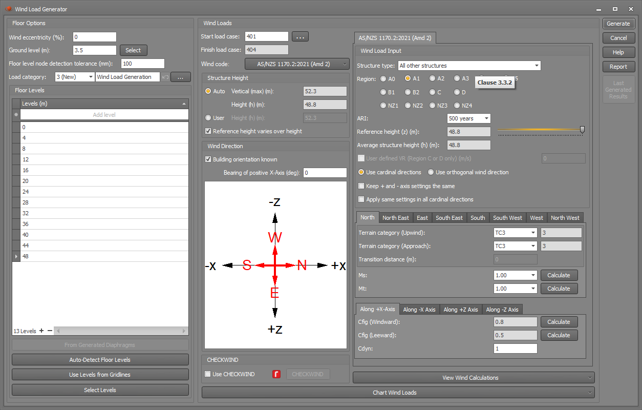
Wind load generator
This tool allows you to generate wind loads on enclosed multi-storey buildings. The wind loads are calculated over the height of the building and then applied to the perimeter nodes at each specified floor level.
Before starting the wind load generation, it is a good idea to define the floor levels in the building by using the gridlines tool. This just makes everything clear and means that the wind load tool doesn't have to scan the model to try to auto-detect the floor levels.
You can run the tool by selecting "Generate Wind Loads" from the "Loads" menu or from the popup menu that appears if you right-click anywhere in the graphics area. The following form then appears that lets you specify the generation parameters.
Wind eccentricity
Wind loading codes generally require a wind eccentricity to be included in the wind load calculations for buildings over a certain height or certain horizontal aspect ratio. For example, AS1170.2 clause 2.5.4 requires an eccentricity of 20% of the overall building dimension normal to the wind direction for buildings over 70m in height. The wind eccentricity is measured relative to the centre of geometry of the building.
Ground level
Specifying the ground level accurately is important because it is used to determine which levels are above ground and which (if any) are below ground. If there are no levels at or below ground level then any wind loads applied at or below ground level and half way up to the first floor are discarded.
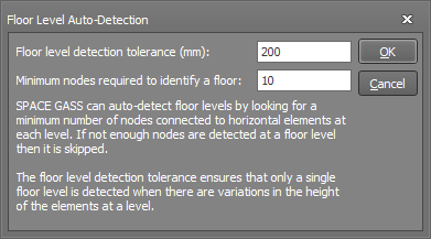
Floor level node detection tolerance
This tolerance is to allow for any variation in the vertical position of nodes in a floor. Nodes that are located within this tolerance from a specified floor level will be treated as part of the floor. You may need to increase it if you have step-downs or changes in elevation over part of a floor.
Load category
This field lets you specify which load category any generated wind loads will go into. For more information refer to "Load categories".
Floor levels
Wind loads are generated for each floor level specified in this table. If you have already generated some diaphragms then the "From Generated Diaphragms" button transfers the levels from that tool into the "Levels" table. Similarly, if you have already defined some gridlines then the "Use Levels from Gridlines" button transfers the gridline levels into the "Levels" table. If you want to select the levels graphically then you can click the "Select Levels" button and then click a node at each level to have it put into the table. Finally, the "Auto-Detect Floor Levels" button looks for a minimum number of horizontal elements in a plane that would identify a floor. You can set a tolerance that allows for some variation in the height of the elements, plus you can control how many nodes within that tolerance are required to identify a floor level.
Start and finish load cases
These are the load cases that the generated wind loads will be put into. If there is no eccentricity then four wind load cases are generated, one for each wind direction. If an eccentricity has been specified then an additional eight load cases are generated for the positive and negative eccentricities in each direction. You can control their numbering via the "Start load case" field. The "Finish load case" is calculated and displayed automatically.
Wind code
You can choose between AS/NZS 1170.2:2021 and IS 875 (Part 3) : 2015, with support for other wind codes to be added in the future.
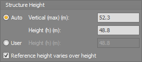
Structure height
If "Auto" is ticked then the "Average building height above ground" (h) is calculated from the maximum detected building height "Vertical (max)" less the specified "Ground level". If this is not suitable then you can select "User" and specify the building height manually.
If "Reference height varies over height" is ticked then the reference height (z) of the windward walls for the level under consideration is taken as its height above ground, whereas if unticked then z = h. For the leeward walls z = h regardless.
Wind direction
If you specify the building orientation then the wind will be calculated accurately for each of the building's orthogonal directions. If the building orientation is unknown then a slightly conservative approach is taken with any direction specific parameters such as Md in AS1170.2.
CHECKWIND
If you have the integrated version of CHECKWIND, you can tick the "Use CHECKWIND" option to calculate the design wind speeds together with the terrain, topographic, direction and shielding multipliers for the key wind directions. If you don't have CHECKWIND then you can still operate it but in a restricted evaluation mode that limits you to a specific site location and structure height. For more information, refer to CHECKWIND.
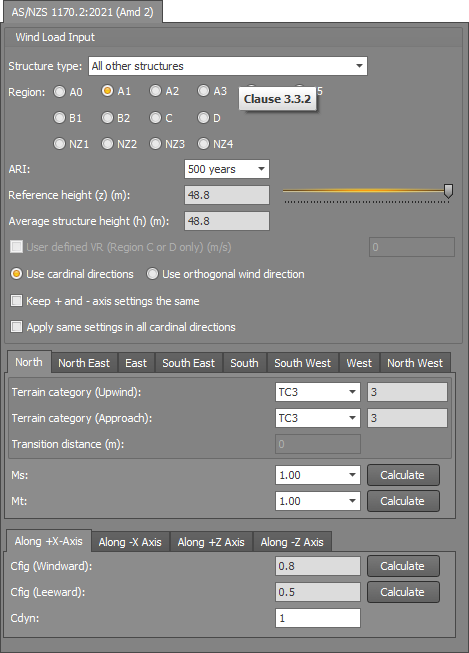
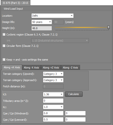
Code specific wind parameters
You should refer to the relevant wind code for details of the code specific wind parameters shown below.
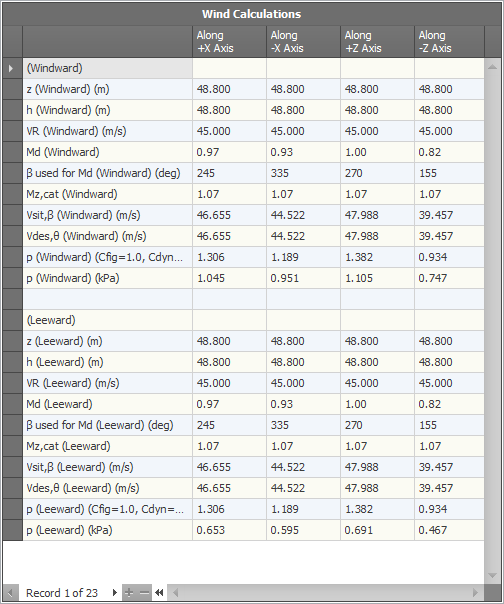
Wind calculations
At any stage, you can click the "View Wind Calculations" button to view the calculated factors and possibly compare them with your own manual calculations.
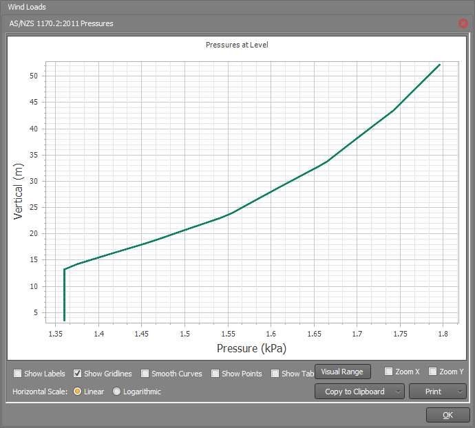
Wind Load Chart
By clicking the "Chart Wind Loads" button you can display a graph that shows how the lateral wind pressure is applied up the building.
Report
At any stage you can click the "Report" button to get a report of the wind load settings.
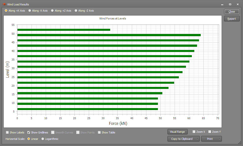
Last generated results
If some wind loads have already been generated, you can click the "Last Generated Results" button to see a chart of the wind loads that were applied to each floor level. The chart also includes a "Report" button that gives you a detailed report of the calculations involved.
See also Wind calculator.