Portal frame loads for AS/NZS1170.2
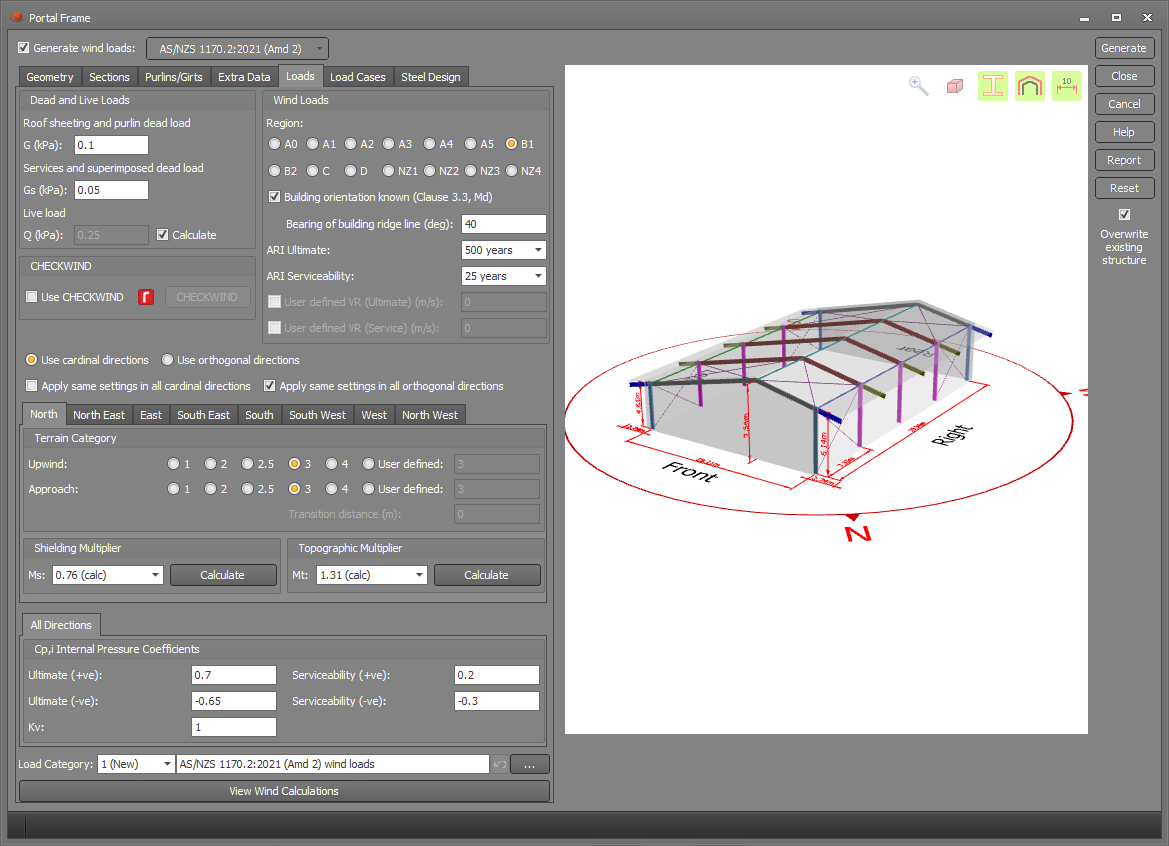
This form contains the code specific dead load, live load and wind load parameters if you have chosen AS/NZS 1170.2 as the wind code.
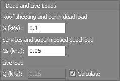
Dead and live loads
The "Roof sheeting and purlin dead load" is a permanent load that is applied to all load combinations, whereas the "Services and superimposed dead load" is considered to be a temporary load that is only applied to the downward load combinations. The dead loads you input are applied to the actual roof area.
The live load is applied to the plan projection of the roof area. If the "Calculate" option is ticked then the live load will be calculated based on the maximum of 0.25 and 1.8/A + 0.12 kPa as given in AS/NZS 1170.1 table 3.2. Note that the distributed live load is applied to the entire roof area, even if the roof area is greater than 200m^2. The 1.4kN concentrated live load specified in AS/NZS 1170.1 (but not in conjunction with the distributed live load - see AS/NZS 1170.1 section 3.1) is not applied.
If the "Calculate" option is unticked then the live load pressure you specify will simply be applied to the entire roof with no extra AS/NZS1170.1 clauses taken into account.
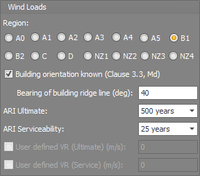
Wind loads
Wind loads can be calculated for any region in Australia or New Zealand. The average recurrence intervals (ARIs) for the ultimate and serviceability limit states are used to calculate the regional wind speeds from AS/NZS 1170.2 table 3.1.
If you specify the building orientation then the wind direction multiplier (Md) will be set in accordance with AS/NZS1170.2 section 3.3. If the building orientation is unknown then for some regions the Md multiplier will be conservatively set to 1.0.
The building orientation is defined by the bearing of a vector along the ridge line pointing from the rear of the building towards the front. For example, a building with a bearing of 0 degrees would have its front wall facing north and its left wall facing east, whereas a bearing of 90 degrees would correspond to the front wall facing east and the left wall facing south. If the building orientation is unknown then slightly conservative "worst case" values will be used for some factors such as Md.
CHECKWIND
If you have the integrated version of CHECKWIND, you can tick the "Use CHECKWIND" option to calculate the design wind speeds together with the terrain, topographic, direction and shielding multipliers for the key wind directions. If you don't have CHECKWIND then you can still operate it but in a restricted evaluation mode that limits you to a specific site location and structure height. For more information, refer to CHECKWIND.
Direction specific parameters
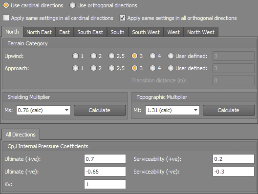
Parameters such as the terrain category, shielding multiplier and topographic multiplier can be specified for each cardinal direction or orthogonal direction. Otherwise you can input the parameters once and have them apply to all directions using the "Apply same settings in all cardinal directions" or "Apply same settings in all orthogonal directions" checkboxes.
Internal pressure coefficients can be specified for each orthogonal direction or just once for all wind directions if you untick "Apply same wind in all directions".
Terrain category
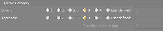
The terrain category affects the terrain height multiplier Mz,cat (see AS/NZS 1170.2 section 4.2). Mz,cat can be based on a single terrain category or it can be an averaged value if the terrain category changes on the upwind side of the structure. SPACE GASS allows for averaging two terrain categories in accordance with AS/NZS 1170.2 section 4.2.3.
Note that the "Approach" TC is closer to the structure than the "Upwind" TC and the "Transition distance" is the distance from the structure to the point where the terrain category changes.
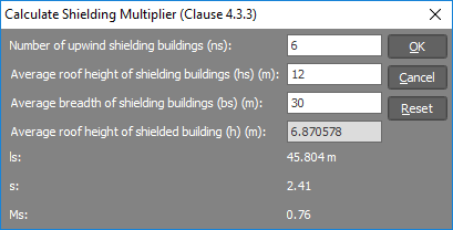
Shielding multiplier (Ms)
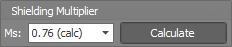
The shielding multiplier Ms (see AS/NZS 1170.2 section 4.3) takes into account shielding provided by other upwind buildings or structures. It is 1.0 if there is no shielding. You can choose between a selection of predefined values or you can click the "Calculate" button and then input various shielding parameters and have Ms calculated for you. The ns, hs, bs and h values and the calculation of Ms are all explained in AS/NZS 1170.2 section 4.3.
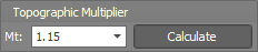
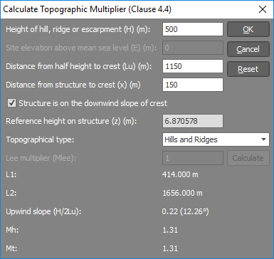
Topographic multiplier (Mt)
The topographic multiplier Mt (see AS/NZS 1170.2 section 4.4) takes into account the topography and its effect on the wind that is applied to the structure. It is 1.0 if there are no topographic effects. You can choose between a selection of predefined values or you can click the "Calculate" button and then input various topographic parameters and have Mt calculated for you. The H, E, Lu, x and z values and the calculation of Mt are all explained in AS/NZS 1170.2 section 4.4.
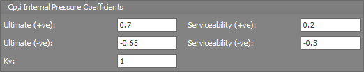
Internal pressure coefficients (Cp,i)
In order to take into account openings, you can define the Cp,i pressure coefficients for maximum pressure (+ve) and maximum suction (-ve). These coefficients are then used when factoring the Cp,i=1.0 internal pressure primary load cases into the ultimate and serviceability combination load cases. If AS/NZS 1170.2 section 5.3.4 applies then you must also manually calculate and specify Kv.
Load category
The "Load category" field lets you specify which load category the generated loads will go into. For more information refer to "Load categories".

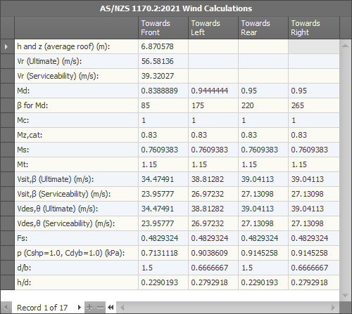
Wind calculations
At any stage, you can click the "View Wind Calculations" button to view the calculated factors and possibly compare them with your own manual calculations.