Portal frame loads for IS875
This form contains the code specific dead load, live load and wind load parameters if you have chosen IS875 (Part 3) as the wind code.
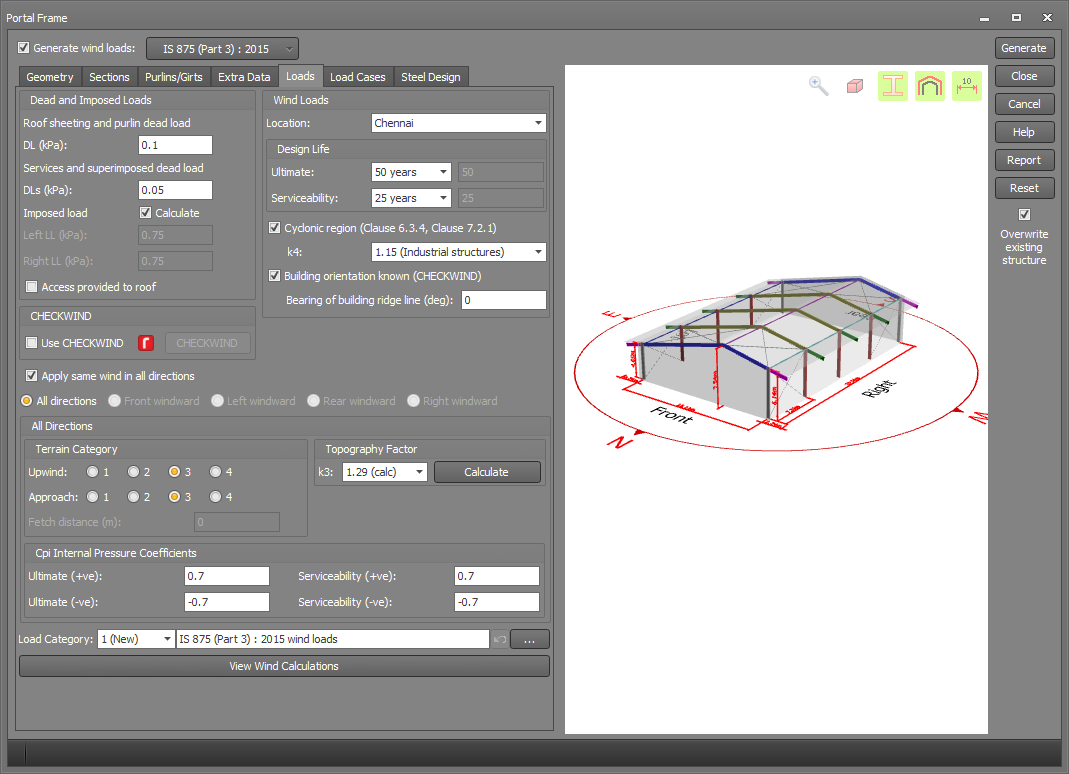
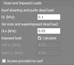
Dead and imposed (live) loads
The "Roof sheeting and purlin dead load" is a permanent load that is applied to all load combinations, whereas the "Services and superimposed dead load" is considered to be a temporary load that is only applied to the downward load combinations. The dead loads you input are applied to the actual roof area.
The imposed load is applied to the plan projection of the roof area. If the "Calculate" option is ticked then the imposed load will be calculated based on the rules in IS875 (Part 2) table 2, but with no extra allowance for rain, dust or the 0.90kN incidental concentrated load specified in IS875 (Part 2) section 4.5.
If the "Calculate" option is unticked then the imposed load pressures you specify will simply be applied to the entire roof with no extra IS875 (Part 2) clauses taken into account.
The "Access provided to roof" option affects whether IS875 (Part 2) table 2(i)(a) or table 2(i)(b) is used for roofs with slopes up to 10 degrees. It applies only when the "Calculate" option is ticked.
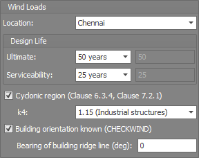
Wind loads
The site location determines the basic wind speed Vb in accordance with IS875 (Part 3) annex A.
The design life affects the probability factor k1 (risk coefficient) (see IS875 (Part 3) section 6.3.1) and you can choose between a design life of 5 years for temporary structures, 25 years for structures presenting a low degree of hazard to life in the event of failure, 50 years for all general buildings and structures or 100 years for important structures. Alternatively you choose "Other" and then specify any other design life for structures that don't exactly conform to one of the pre-defined structure types. The k1 factor is then calculated based on the basic wind speed and the design life in accordance with the formula given in IS875 (Part 3) table 1.
If the location is in a cyclonic region then you must also select the importance of the structure so that the importance factor k4 can be calculated from clause 6.3.4. Note that by ticking "Cyclonic region" you are also affecting the calculation of the wind directionality factor Kd based on clause 7.2.1.
The building orientation is only required by CHECKWIND and is defined by the bearing of a vector along the ridge line pointing from the rear of the building towards the front. For example, a building with a bearing of 0 degrees would have its front wall facing north and its left wall facing east, whereas a bearing of 90 degrees would correspond to the front wall facing east and the left wall facing south. If the building orientation is unknown then slightly conservative "worst case" values will be used for some of the factors calculated by CHECKWIND.
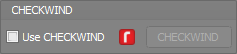
CHECKWIND
If you have the integrated version of CHECKWIND, you can tick the "Use CHECKWIND" option to calculate the design wind speeds together with the terrain, topographic, direction and shielding multipliers for the key wind directions. If you don't have CHECKWIND then you can still operate it but in a restricted evaluation mode that limits you to a specific site location and structure height. For more information, refer to CHECKWIND.
Direction specific parameters
Parameters such as the terrain category, topography factor and internal pressure coefficients can be specified just once for all wind directions or, if you untick "Apply same wind in all directions", then you can specify different parameters for each of the four orthogonal wind directions.
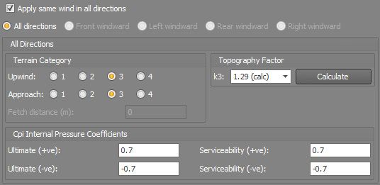
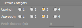
Terrain category
The terrain category affects the terrain and height multiplier k2 (see IS875 (Part 3 section 6.3.2). k2 is calculated from IS875 (Part 3) table 2 and also depends on the building height. k2 can be calculated from a single terrain category or it can be an averaged value if the terrain category changes on the upwind side of the structure. SPACE GASS allows for averaging two terrain categories in accordance with IS875 (Part 3) annex B.
Note that the "Approach" TC is closer to the structure than the "Upwind" TC and the "Fetch distance" is the distance from the structure to the point where the terrain category changes.
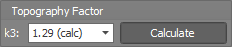
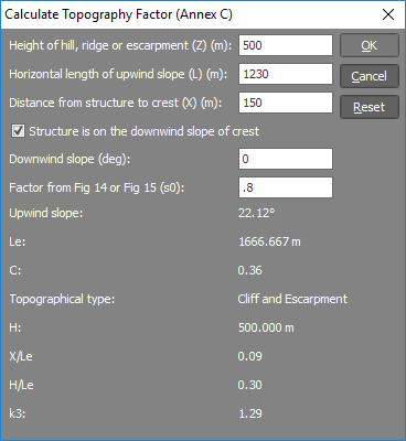
Topography factor (k3)
The topography factor k3 (see IS875 (Part 3) section 6.3.3) is affected by a hill, ridge or escarpment in the vicinity of the structure. You can choose between predefined values of 1.00 or 1.36 or you can click the "Calculate" button and then enter various parameters to have the k3 factor calculated for you. The Z, L, X and s values and the calculation of k3 are all explained in IS875 (Part 3) annex C.
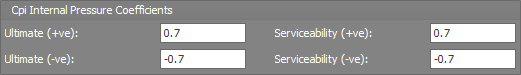
Internal pressure coefficients (Cpi)
In order to take into account openings, you can define the Cpi pressure coefficients for maximum pressure (+ve) and maximum suction (-ve). These coefficients are then used when factoring the Cpi=1.0 internal pressure primary load cases into the ultimate and serviceability combination load cases.
Load category
The "Load category" field lets you specify which load category the generated loads will go into. For more information refer to "Load categories".

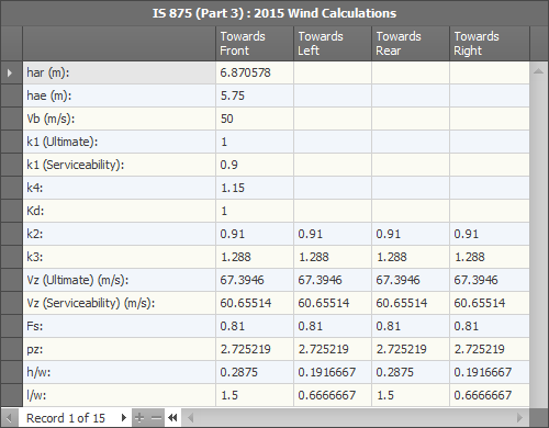
Wind calculations
At any stage, you can click the "View Wind Calculations" button to view the calculated factors and possibly compare them with your own manual calculations.