Portal frame member design
This worked example considers the AS4100 member design of the 25m span haunched portal frame which was analysed in the previous appendix. The design is based on the non-linear analysis results of the combination load cases 10 - 14.
This appendix considers only the design of the portal frame members. The portal frame analysis and connection design is covered in Portal frame analysis and Portal frame connection design.
This example bases the member design directly on the forces and moments obtained from the non-linear analysis. The non-linear analysis results for combination load cases 10 - 14 are included in the static analysis report (itemised) of the portal frame analysis worked example.
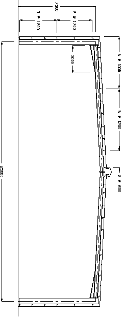
The portal frame has wall girts spaced at 1200mm and 1700mm, and roof purlins spaced at 1000mm, 1200mm and 800mm as shown in the following drawing. The frame is fully symmetrical about its centre.

In order to check deflections, the following maximum limits will be used.
|
Eaves sway limit for serviceability: h/150 |
|
Apex sag limit for dead load: L/360 |
|
Apex sag limit for live load: L/240 |
|
Apex deflection limit for: L/150 |
|
serviceability: |
|
|
|
Eaves sway due to cross wind: 99*(38/60)**2= 40mm = h/188 (Ok). |
|
(Vu = 60m/s, Vs = 38m/s) |
|
Apex sag due to dead load: 36mm = L/694 (Ok). |
|
Apex sag due to live load: 66mm = L/379 (Ok). |
|
Apex uplift due to cross wind (96+109)*(38/60)**2 = 82mm = L/305 (Ok). |
|
and internal pressure: |
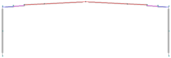
In order to define the steel member design data for the frame, the following design groups were specified.
|
Group 1: |
Left column |
Members 1 and 2 |
|
Group 2: |
Left rafter |
Members 3, 4, 5 and 6 |
|
Group 3: |
Right rafter |
Members 7, 8, 9 and 10 |
|
Group 4: |
Right column |
Members 11 and 12 |
(Haunches have to be checked by hand)
Groups 3 and 4 were specified as members 10,9,8,7 and 12,11 (rather than 7,8,9,10 and 11,12) so that the positions and types of flange restraints could be referenced from the column base and the narrow end of the haunch in similar fashion to groups 1 and 2. This was not absolutely necessary, however it made the input of the restraint data for groups 3 and 4 identical to the data for groups 1 and 2.

In the diagram above, the thick grey lines show the four design groups. They are drawn short of their ends so that you can easily see where they start and finish.
Even though the haunches can’t be design or checked (because of their varying properties and non-standard shape), they have been included in the rafter groups 2 and 3. They have, however, been excluded from the portion of the rafter being designed or checked by using an I (ignore) zone in the flange restraint data. If the haunch members had simply been omitted from the rafter groups then the group lengths would have been shorter and the compression and bending effective lengths could have been underestimated.
All compression effective lengths were calculated by the buckling analysis and automatically transferred into the member design. The advantage of doing it this way is that different effective lengths can be used for each design load case. The alternative is to manually input the effective lengths, however they are then used for every design load case and the design is usually not as efficient.
The minor axis (out-of-plane) compression effective lengths were also specified as being braced at each end due to wall and roof bracing that prevents any out-of-plane buckling at the rafter ends. This has the effect of limiting the minor axis compression effective lengths to no longer than the rafter group length.
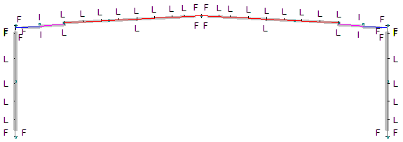
Flange restraints for the columns were placed on the outside (top) flange at each end and at each girt location. Inside (bottom) flange restraints were placed at the column ends. There are no column fly braces and therefore no intermediate inside flange restraints were applied.
For each column, the column base plate was assumed to provide full restraint to both column flanges and hence restraint codes of F (full) were specified for both column flanges at the base.
Because wall bracing and an eaves strut effectively prevented lateral deflection of both flanges at the top of the column and because the rafter provided partial (or full) twist restraint, the restraints applied to the top of the column were assumed to be F (full).
In addition, the stiffness of the haunch meant that the restraining effect of the rafter could be considered to be applied at the bottom of the haunch, hence additional flange restraints identical to those at the top of the column were applied to both column flanges at the base of the haunch. An I (ignore) continuous restraint was also applied to the segment from the bottom of the haunch to the top of the column so that it would be ignored during the design.
Top flange restraints of L (lateral) were positioned at each purlin location in the rafter design groups, except that the purlins close to the end of the haunch and near the apex were conservatively assumed to be at the ends of the haunch and at the apex. Bottom flange restraints were also positioned at the ends of the haunch and at midspan of the rafter design groups to coincide with fly braces at those locations. Restraint codes of I (ignore) were positioned between the first two rafter flange restraints so that the haunches could be excluded from the calculations.
Fly braces were located at the face of the columns and at the apex, and hence the top and bottom flange restraints at the ends of the rafter design groups were assumed to be at least F (full).

The above diagram shows the location and type of all the flange restraints.
Note that the effect of the fly brace at midspan could also have been taken into account by specifying a full restraint at the fly brace location on the top flange and not specifying anything on the bottom flange. A full or partial restraint on one flange causes SPACE GASS to automatically place a partial restraint (at least) on the other flange (see also Effective flange restraints). This method would, however increase the kt factor marginally.
All of the member design data was input graphically, however it could have been input just as successfully via a datasheet or by importing it from a text data file. For information about the graphical input procedure for steel member design data, see also Steel member input methods. For detailed information about the actual member design data values and settings, see also Steel member design data.